Sensors are the eyes and ears of your robot or Programmable Logic Controller. They allow your controller to determine the state of objects in and the environment around your automated operations. There are many differences between the wide variety of sensors on the market. You can buy sensors that are inductive, magnetic, photoelectric, or ultrasonic. You can buy sensors that sense parts that are very close, or parts that are quite far. Sensors can be big, or small. You can find sensors that detect a range of materials, detect only ferrous metals, detect only magnets, or even that detect materials inside of other containers. Among all of these varieties, one of the most fundamental differences between proximity sensors is whether the sensor provides a digital or analog output. In this article, I’ll discuss the difference between analog and digital sensors, and why you would choose one or the other.
Contents
- Using Sensors To Tell A Controller What’s Out There
- Digital Sensors
- Analog Sensors
- Additional Information
BTW, make sure you don’t miss out on content like this in the future! Take a moment to sign up for my email list below. You can expect about 1-4 emails per month with content related to automation.
Using Sensors To Tell A Controller What’s Out There
In the world of industrial automation (and in other settings, like home automation, Arduino development, etc.), a huge variety of sensors exists. Sensors provide feedback about the automated process to the PLC or other process controller. Imagine parts moving down an assembly line in a factory:
As each part moves down the line, the PLC must know the part’s location to know when it is time to perform each portion of the manufacturing process. But how can we tell a microcontroller where objects are in the real world? With sensors, we can determine where objects are located.
Additionally, we can validate that the correct object is located where we expect. For instance, you may have a station where two different – but similar – parts are loaded for further assembly. Sensors can confirm both that a part was loaded and that the right part was loaded. Take a look at the application shown below:

Applications For Analog And Digital Sensors
In the case above, the controller only needs one piece of information from each sensor: is the sensor “made” or not?
What Does It Mean For A Sensor To Be “Made”?
What does someone mean when they say that a sensor is “made”? This means that the sensor “sees” whatever it is supposed to detect. In the scenario above, we’re using photoelectric sensors to detect the presence of the parts on the conveyor. Photoelectric sensors of this type emit a beam of laser light and wait to see if this light reflects back to the receiver.
In the case above, each sensor is “made” if its receiver detects a sufficient quantity of the reflected light. Different sensors have different detection mechanisms. There are surely dozens of detection methods, but around 5 common ones. For more information on that subject, check out this article on the different types of proximity sensors and their detection mechanisms.
When Are Digital Sensors Used?
Continuing with the previous thought, the controller only needs to know one thing from the sensors above: do they or do they not see a part?
More specifically, a PLC or other controller would only need one bit of information from each sensor. Is the sensor ON (made: a part is present), or is it OFF (not made: no part is present)?
We refer to sensors or other devices that only output one bit as digital sensors. Digital sensors will have (at a minimum) one signal wire that will either be energized or not energized, based on whether the sensor is made. More on that below.
When Are Analog Sensors Used?
Let’s imagine a slightly different scenario. Let’s say that, at the sensor station on this conveyor, a robotic arm would come down and pick up each can as it passed by.
Because there is a little bit of variance in the left-to-right position of each pallet on the conveyor, the cans won’t be in exactly the same place every time. As a result, the robotic arm may have a hard time picking up each can, as the robot attempts to pick from the same position every time.
One way to solve this problem would be to use a sensor that could tell the controller how far away the cans are from the sensor station. This would provide the can’s location along the horizontal axis of the conveyor. With this information, the controller could provide more specific positional data to the robotic arm. This “offset” to the robot would allow it to pick the cans reliably.

Analog Sensors Provide Precise Feedback
For this type of application you would need an analog sensor. Analog sensors provide specific feedback along some scale. This feedback could correlate with distance (as in this case), pressure, temperature, or other data. In each case, though, an analog sensor would provide a specific value back to the controller, instead of just an on or off condition.
In the case shown above, an analog sensor could provide feedback to the controller not only in terms of whether a part is present, but also in terms of how far away the part is. This type of sensor (a photoelectric or ultrasonic sensor that reports the distance to an object) is referred to as a “time of flight” sensor.
Digital Sensors
As mentioned above, a sensor is digital if its output only has two possible states: on or off. The most basic of this type of sensor will typically have 3 wires coming into it:
- A power wire (typically +24VDC in modern industrial automation)
- A neutral wire (0VDC)
- A signal wire (provides feedback to a PLC or other controller)
A digital sensor will output one of two possible states on its signal wire:
- On (the sensor energizes the signal wire with voltage and a small amount of current)
- Off (no voltage on the signal wire)
The sensor changes its output state when it detects a part. The controller monitors the sensor’s output state via the signal wire. When do you think the sensor will energize the signal wire? If it sees a part, or if it does not see a part?
Normally Open Prox Sensors
To me, the intuitive answer is that a “prox” sensor’s signal wire will be energized when the sensor is made. The sensor sees a part (or senses whatever it was that it was designed to sense), and then it outputs a signal back to the PLC. “Hey, I see something!”

This type of output scheme is referred to as Normally Open, or “N.O.”.
- Normal: The typical state of the sensor, which is to say, when the sensor is not made
- Open: The sensor’s output circuit is “open”, meaning that the sensor has de-energized its signal wire (no voltage present)
The most basic (and common) type of proximity sensor you will see, in my experience, is a Normally Open inductive proximity sensor with a single output.
Normally Closed Prox Sensors
It is not uncommon, however, to see sensors with an inverted output scheme to the one above. To many people, myself included, this sensor works “backwards” to what’s intuitive. This sensor’s output is on by default and only turns off when the sensor is triggered.
Normally Closed sensors have many applications. For instance, many safety circuits are Normally Closed. As mentioned above, “N.C.” sensors provide output voltage constantly, until the sensor detects something.
When you perform electrical troubleshooting, you soon figure out that opens (breaks in a wire) are more common than shorts (when an unintended source energizes a wire). NC sensors and circuits are good for situations where you want to know that something is working at all times, instead of finding out only when it’s time to detect something that the sensor or its wiring has failed.
Normally Closed Proximity Sensor Applications
For instance, consider fire detection. Let’s go for fire detection around an aircraft engine. If I’m designing a safety circuit for an aircraft engine bay, I really want to know if there’s a fire in there. Typically, there won’t be a fire in there. So, typically, my fire detection sensor is sitting around idly – it is not reporting that there is a fire.
Well, what happens if there is a fire? Is my sensor working properly? Is there damage to its cables? Has a wiring harness that passes its signal back to the cockpit come loose?
If I only report a signal when I detect something, as is the case with Normally Open sensors, then I only know if there’s a problem when there is a fire, but no alarm!
Normally Closed, sensors, on the other hand, provide a signal back to the controller all the time. They only de-energize the signal if they’re made. Because NC sensors provide constant voltage back to the controller, I will immediately know if an NC sensor has failed due to damage or wiring issues. This is because a loss of signal, which is the more common electrical failure, looks the same as a Normally Closed sensor that is operating normally and made.

How I Conceptualize Normally Closed Sensors
To summarize, NC sensors energize their outputs normally, and only de-energize their outputs when they are made. For this reason, I have come to think of the behavior of NC sensors as follows: “I’m safe, I’m safe, I’m safe, hey – I see something! <drops the output signal>”
To learn more on this topic, check out this in-depth post on the concepts of Normally Open and Normally Closed.
Digital Sensors With Both Normally Open And Normally Closed Outputs
Alright, we’ve covered the layups above, now let’s go for the 3-pointer:
How do you know if a Normally Open sensor has failed, or if its cabling is damaged?
Well, its output is normally off, so you only know if an NO sensor has failed when it is supposed to be indicating that it is made, but it’s not indicating.
But what if you had a sensor that provided one indication when it was made, and a different indication when it was not made?
The most robust digital sensors, in my opinion, are sensors which have both NO and NC signal outputs. Sensors of this type have “complementary outputs”. Let’s dive into that just a bit:
When wiring sensors for industrial automation, you’ll often find the following color code used:
| Pin | Wire Color | Purpose |
|---|---|---|
| 1 | Brown | Power (+24VDC) |
| 2 | White | Signal 2 |
| 3 | Blue | Common (0VDC) |
| 4 | Black | Signal 1 |
Prox Sensors With Complementary Outputs
With a basic NO or NC prox, only the Signal 1 cable provides feedback to the PLC. When you’re using a prox with complementary outputs, however, there will always be a signal back from the sensor to the PLC. This is because one signal wire is N.O., and the other signal wire is N.C. When Signal 1 is energized, Signal 2 is de-energized, and vice-versa.
For this reason, with a prox with complementary outputs, there will always be a signal present at the PLC. While other failures are possible, this at least covers an open circuit, which is the most common type of electrical defect. Complementary outputs ensure that the PLC will at least know that the sensor is communicating.
With all of this said, proxes with just one output (NO or NC) are much more commonly used in industrial automation than proxes with complementary outputs.
Digital Sensor Applications
What Do Digital Sensors Detect, Conceptually?
When will you use a digital sensor? Well, most of the time, is the answer. Sensors with digital outputs are the typical type of sensor used in manufacturing and automation. Digital sensors have a simplistic, on/off output circuit. For this reason, we use digital sensors where binary conditions exist:
- Material is either present or not present
- Temperature or pressure is either higher than a certain value, or not
- A tank is full, or not
- Parts are aligned or are out of alignment
- A cylinder is in a certain position, or not
The most common sensor used in manufacturing, in my experience, is an inductive proximity sensor with a Normally Open digital output. It’s about as basic as a sensor could be. This is meant both in terms of the sensor itself and in terms of wiring it to the PLC.
Real-Life Applications For Digital Sensors
With this in mind, however, note that even though a digital output circuit is simple, the sensor’s processing circuit can be complex. For instance, some vision systems can provide a digital output if the camera detects a certain object in its image. Many pressure sensors, time-of-flight sensors, and other devices trigger their digital outputs at a certain threshold value for pressure or distance. The user can often program this threshold.
In keeping with the above, here are some digital sensor applications:
- Part present sensing
- Error-prevention (keeping someone from loading the wrong part) by validating that a certain feature of the part is there or not there
- Tank full or tank empty
- Cylinder extended, cylinder retracted
- A particular side of a rotating assembly is in position
- Pressure or temperature above or below a specific value
- Button pressed or released
- Door open or closed
- Mechanical overtravel (a prox placed just beyond the normal motion of a machine to detect when something has gone awry)
- Personnel safety (light screen clear, safety mat clear, etc.)
Analog Sensors
Now that that’s out of the way, let’s get back to the differences between digital and analog sensors. Above, you read that digital sensors are the more common type of proximity sensor. Digital sensors are, often, very straightforward and to-the-point to implement in your process.
One difference between digital and analog sensors is that analog sensors often require more programming to integrate with your PLC, robot, or controller. In exchange for this, they offer precision feedback that digital sensors are unable to provide.
Analog Outputs
A sensor with digital outputs only conveys a “0” (off) or a “1” (on) to the PLC. The primary manner in which analog sensors differ from digital sensors is their output scheme.
Unlike digital sensor outputs, which are either on or off, analog outputs convey a range of values. This range will typically correlate on a linear scale to the range of pressures, temperatures, or distances that the sensor can detect. Let me break that down:
An Example Of An Analog Sensor
Take a look at the following analog pressure sensor:
Telemecanique WMLP100PD230 Pressure Sensor
This pressure sensor is a device that senses the pressure in some hose or pipe. Note the following details from the product’s specifications:
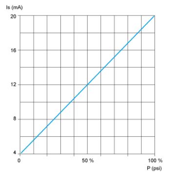
- Gauge Range: 0-100 PSI
- Analog Output: 4-20 mA
Analog Sensor Specifications
The numbers above are pretty critical bits of data about the operation of this analog sensor. What these specifications are telling you is that the sensor is able to report back specifically how much pressure it detects. The limits to its pressure sensing range are, obviously, 0 and 100 Pounds per Square Inch.
In order to provide feedback to the PLC, the sensor will output a specific current that corresponds with the amount of pressure it senses. The analog output range tells you the current range that will correspond to the pressure sensed. In this case, the sensor will output between 4 and 20 milliamps of current.
The current output will correlate to the pressure sensed. In many cases, the smallest value of voltage or current feedback will correspond with the smallest limit to the sensing range. This is not always the case, however, and so you must check the datasheet for an analog sensor to determine its functionality.
Analog Sensor Datasheets
To figure out how our analog sensor works, let’s take a look at its datasheet:
On Page 1, you’ll find the “Analog output function” and “Pressure setting range” values that correspond to the numbers you saw above.
On Page 4, you’ll see how to wire the sensor to the PLC or other controller. Page 4 shows the sensor’s “pin-out”. There are pins on the sensor’s connector that connect to outside wiring for power and feedback. The pin-out tells you which of the connector’s pins connect to outside wiring. Additionally, it tells you what the outside wiring needs to connect to.
Now, take a look at Page 5. On this page, you’ll see a graph of the sensor’s output value as it corresponds to various input (pressure) values. Note that the graph is a straight line. This tells you (assuming the unit scales are linear, anyway) that there is a linear correlation between pressure and current output.
With this in mind, you can easily calculate the pressure in the field based on the sensor’s analog output. Which is key, as this is precisely what you would need to do to develop logic for this sensor in your PLC program.
Analog I/O Considerations
There’s one additional consideration when using sensors with analog outputs. That consideration is the availability of analog inputs to which your analog sensors must be connected.
Virtually every PLC will come with digital inputs. In other words, it is virtually guaranteed that you will be able to hook up at least some number of digital sensors to your PLC or controller. Typically, you will be able to do this for digital sensors “out of the box”. By this, I mean that digital sensors can be “hooked right up”. The PLC can access the sensors’ inputs, and monitor signals right away.
Analog sensors provide analog outputs. An analog output from your sensor has to hook up to an analog input to talk to your PLC. Most input ports will accept either digital or analog inputs, but not both. As mentioned above, most PLC’s accept digital inputs out of the box. Not all PLC’s accept analog inputs natively.
So, to use your analog sensors, you must have:
- A PLC with analog inputs built in
- An add-on analog input card that you can connect to your PLC
- A separate “input block” that connects to your sensor, which then talks to the PLC
In most scenarios, it won’t be difficult to find a solution for hooking up analog inputs to your PLC. With that said, it is something to consider when adding analog sensors to an automated process.
Analog Sensor Applications
So, when would we use analog sensors? Analog sensors are more difficult to program and integrate than digital sensors. However, they provide feedback to the PLC that digital sensors cannot provide.
Analog sensors give you precise feedback. Use an analog sensor:
- When it’s necessary to know not just that a part is there, but how far away the part is
- If you need to know not just whether a tank is full or empty, but how full or empty it is
- If you want to monitor specific temperature or pressure
With those concepts in mind, here are some applications for analog sensors:
- Alignment check (verifying a part is in a specific position) with a photoelectric time-of-flight sensor
- Predictive maintenance: monitoring for rises in temperature or vibration
- Motor speed control based on the amount of liquid in a tank
- Distance-sensing via an ultrasonic time-of-flight sensor to allow a robot to approach a part that is an unknown distance away
- Light sensors
- Cylinder extension detection using analog magnetic sensors
Additional Information
I hope I’ve shed some light above on the differences between digital and analog sensors. Selecting, setting up, wiring, and configuring sensors is a key skill-set for Industrial Automation Engineers and Technicians. Similarly, understanding the difference between analog and digital sensors and outputs is part of the foundation of knowledge you will need to succeed in automation.
For additional information on the differences between digital and analog sensors, and on proximity sensors in general, check out the following resources:
- A couple from yours truly:
- A nice little write-up on analog vs digital sensors and sensor types from Codrey.com
- Some quality content on the concepts of analog and digital from TurboFuture.com. In addition, the author goes a bit into signal processing
- Lastly, an interesting analog/digital article from Electronics-Tutorials.ws. Additionally, this article includes some information on transducers and sound
Do you have any lingering questions about proximity sensors, or other topics related to industrial automation? Head down to the bottom of the page and leave a comment. If you’ve got a great question, I may just write an article in response!
Thanks for reading!! 🙂