When you write logic in a PLC that initiates motion, you want to be certain that the motion you are expecting actually occurs. This is where sensors come into play. Sensors provide indication to the PLC, robot, or other controller that some physical event has taken place. As examples, sensors may detect that a part is present, that a part is not present, that an actuator is in a certain position, that a lift is lowered or raised, that a door is open or closed, or that a spring-returned component is a certain distance away. Proximity sensors are a specific subset of sensors in general. In this article, we’ll look at some of the many different types of proximity sensors that are used in industrial automation.
Contents of this post:
What Is A Proximity Sensor?

Proximity sensors – sometimes referred to as proximity switches – are sensors that are used in industrial automation and other applications. What distinguishes them from other sensors is that they can sense objects without having to touch them. Because they don’t have to physically interact with the objects they detect, proximity sensors often have no moving parts. If you don’t already know, solid-state devices – devices that have no moving parts – often last much longer than devices which have to move to do their job. Wikipedia sums this up as follows:
A proximity sensor is a sensor able to detect the presence of nearby objects without any physical contact.
…Proximity sensors can have a high reliability and long functional life because of the absence of mechanical parts and lack of physical contact between the sensor and the sensed object.
Wikipedia article on Proximity sensors
Advantages Of Solid-State Proximity Sensors
For the reasons above, proximity sensors are very popular in industrial automation. Other types of sensors, such as limit switches, require contact with the part.
Because they have to contact the part, limit switches require moving components. Because they have moving components, they may fail much sooner than a non-contact proximity sensor. For this reason, limit switches and other sensors that require internal motion are becoming less and less common.

Proximity Sensor Types
The zoo of sensors on the market is quite diverse. Although there are other, more obscure sensors out there, I want to go over the types of proximity switches that I see most commonly used in industrial automation:
- Inductive Proximity Sensors
- Capacitive Proximity Sensors
- Magnetic (Hall Effect) Proximity Sensors
- Photoelectric Proximity Sensors
- Ultrasonic Proximity Sensors
Inductive Proximity Sensors

In industrial automation, inductive proximity sensors are one of the most common types of proxes. Inductive proximity sensors have a coil inside of them. The coil and body of the prox are designed to generate an electromagnetic field at the face of the prox. When a target is presented within the prox’s sensing range, the electromagnetic field is dampened. Once this dampening exceeds a certain threshold, the state of the output changes.
I felt a great disturbance in the force
Obi-Wan Kenobi, and inductive proximity sensors
The state of the output changes based on whether you’re using a “Normally Open” or “Normally Closed” sensor. Normally Open (or “NO”, or “N.O.”) sensors have outputs that are normally OFF (“open”). A NO sensor’s output turns ON when the sensor detects its target.
Similarly, Normally Closed sensor outputs are normally ON (“closed”). When an NC sensor sees a target, its output turns OFF. You can read much more about the concepts of NO and NC here.
Digital And Analog Proximity Sensors
The sensors above (NO and NC) are referred to as digital sensors. Digital, in this context, refers to the fact that the sensor’s output is either ON or OFF. In addition to digital sensors, there are analog sensors.
Analog sensors provide feedback as a variable voltage or current output. As the sensor’s target moves closer or further, the output signal increases or decreases. Using an analog sensor, you’re able to tell not just that the part is present, but also how far away the part is.
Click the following link for an in-depth look at the difference between analog and digital sensors.
Inductive Prox Applications
Because inductive proximity sensors utilize electromagnetic fields, they can only detect metallic objects. Within the domain of metallic objects, inductive proximity sensors respond differently to different metals. As sensors in this family have evolved, you can now purchase sensors that respond more sensitively to ferrous metals (such as iron and steel), nonferrous metals (such as aluminum), or sensors that respond to a variety of metals approximately equally.
Turck’s uprox factor 1 sensor has been the standard in the automotive sector for twenty years. The same large switching distances for all metals, weld field immunity and a large degree of mounting flexibility are the key benefits of these inductive sensors without a ferrite core.
From “Smart Switches“, a Turck publication describing their family of inductive proxes that sense different metals equally
The fact that inductive sensors only sense metal objects can be of benefit in many applications. As non-metallic contaminants will be less likely to trigger an inductive sensor, sensors of this type are tolerant of dirt and moisture build-up. For this reason, they’re the go-to choice for detection of metallic components.
Learn More About Inductive Proximity Sensors
- Basic Operating Principle Of An Inductive Proximity Sensor from Automation Insights
- Inductive proximity sensor publication from Schneider Electric
- PC Control’s Inductive Proximity Sensors
- Inductive sensor article on Wikipedia
Capacitive Proximity Sensors

Outwardly, capacitive proxes can be quite similar to inductive proxes. The two types are often available in the same form factors. Where capacitive proximity sensors differ from inductive proxes is in the sensing mechanism. Capacitive proxes work as capacitors. There is an energized metallic plate in the face of a capacitive prox. This plate serves as one side of the capacitor, with the prox’s target serving as the other side.
When a capacitive sensor is exposed to open air, the measured capacitance is low. As an object approaches the prox’s sensing area, the capacitance increases until a threshold is met and the output is set. Like inductive sensors, many capacitive sensors are wired as NO or NC digital sensors, or alternatively as analog sensors.
Capacitive Prox Applications
Whereas inductive sensors generate electromagnetic fields, capacitive sensors generate electrostatic fields. Capacitive sensors are an interesting type of proximity sensor used in manufacturing. Because capacitive sensors detect changes in the capacitance of the field they generate, they have the special property of being able to detect non-conductive materials. Due to this attribute, capacitive proxes can detect plastic, glass, water or other liquids, biological materials, and more.
In fact, capacitive proxes are often used as liquid or solid level detection sensors. Because the sensitivity of many capacitive proxes is adjustable, these sensors can be set up to read the presence or absence of a material through the material’s container.
Learn More About Capacitive Proximity Sensors
- For a general understanding of capacitance, check out Electronics Tutorials’ Introduction to Capacitors
- What are capacitive proximity sensors? by Motion Control Tips
- What is a Capacitive Sensor? by Automation Insights
- Capacitive Proximity Sensors on SolidsWiki
Magnetic (Hall Effect) Proximity Sensors

A magnetic (Hall Effect) proximity sensor. Note that, like inductive and capacitive sensors, magnetic sensors are also available in the barrel form factor, and that the color of the face or threads is no indication of whether the prox is inductive, capacitive, or magnetic. You would need to look up the part number to determine the prox’s detection mechanism.
Magnetic, or “Hall Effect,” proximity sensors are triggered by magnets. As illustrated in the image above, magnetic sensors are available in the barrel form factor, among others. Hopefully you have seen by now that you cannot assume a sensor’s type by its form factor. When buying or “spec’ing” a prox for your company or application, you have to research the part number to be sure of what you’re buying.
Humanity has known of the Hall Effect since the 19th century. Hall Effect switches have been in use since at least the 1970’s. Modern Hall Effect sensors detect the presence and distance of a permanent magnet. With the right setup, magnetic sensors can also detect ferrous metals.
Like inductive and capacitive proxes, magnetic sensors can provide either digital or analog outputs. Digital outputs are either on or off, whereas analog outputs provide a variable voltage or current based on how far the part is from the sensor.
“Reed sensors” bear mentioning in this space. Reed sensors are in many ways equivalent to the solid-state Hall Effect sensor, except that reed sensors have tiny parts inside that move. Because reed switches function very similarly, but have moving parts, I’ve chosen to limit the conversation to Hall Effect sensors.
Magnetic Sensor Applications In Industrial Automation
Magnetic sensors are very common and have many applications across industries – from automotive to aerospace engineering. Within industrial automation specifically, there are several prominent applications for magnetic sensors.

One application is cylinder indication. Pneumatic cylinders are a common means of linear actuation. A linear actuator is a device that moves something from one position to another in a straight line. Pneumatic cylinders that are designed to be used with magnetic sensors have pistons with ring magnets.

When the piston moves within sensing range, the ring magnet’s magnetic field triggers the sensor. This provides indication back to the controller as to whether your requested actuation actually occurred.

Magnetic Position Sensors With Analog Outputs
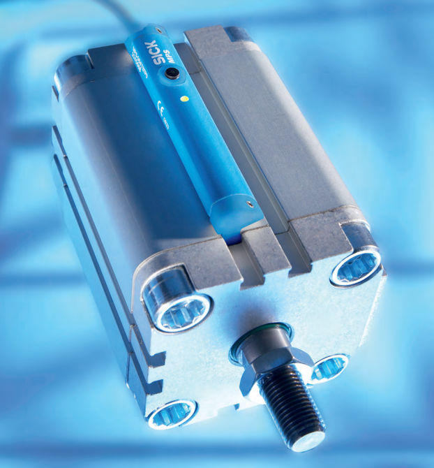
Magnetic sensors with analog outputs (like this Sick MPS-T) can indicate precise positions of pneumatic actuators. Sensors of this type act like LVDT’s, providing high-resolution feedback on the position of the magnet within the sensor’s sensing range. With these sensors, you can observe the position of a cylinder within tenths of a millimeter. That type of resolution allows very precise control of industrial processes.
Another Application For Magnetic Proximity Sensors
There is another application in which you might find this type of proximity sensor used in industrial automation. In certain situations that are difficult for inductive sensors, magnetic proximity sensors can thrive.
The sensing range for inductive sensors is dependent on the size of the sensor. The smaller the face of the inductive proximity sensor, the smaller its sensing range. With small inductive proxes, sensing ranges are in the single digit millimeter and sub-millimeter distances.
Even small magnetic proximity sensors often have sensing ranges much greater than many inductive proximity sensors. For this reason, magnetic sensors are sometimes used where a small sensor is needed, but the target is not very close. If this is the case, a magnet may need to be mounted on the target.
Learn More About Magnetic Proximity Sensors
- For a general understanding of magnetic sensing, check out KJ Magnetics’ Reed Switches and Hall Effect Sensors
- Hall Effect Sensor from Electronics Tutorial
- Sensor Choices for Pneumatic Cylinder Positioning from Hydraulics & Pneumatics
- Honeywell’s Hall Effect Sensing And Application document
- Hall effect sensor on Wikipedia
Photoelectric Proximity Sensors
Photoelectric sensors, or “photo eyes,” are triggered by the presence or absence of electromagnetic radiation. Most commonly, this electromagnetic radiation would be infrared or visible light.
Depending on the type of sensor and application, photoelectric sensors may require some setup. This is due to the many ways in which photoelectric sensors can be utilized and the versatility offered by many sensors in when the sensor will turn on or off its output.
When discussing photo eyes, the concepts of Normally Open and Normally Closed often translate to Dark On and Light On. Depending on how your sensor is configured, Light On generally means that the sensor’s output will only be ON when the emitter’s beam is detected at the receiver. Dark On is the opposite condition.
There are three broad types of photoelectric sensors:
Through-Beam Photoelectric Sensors
Through-beam photo eyes consist of two separate electronic components: an emitter and a receiver. The emitter shines a beam of infrared or visible light. The receiver detects this light and the sensor’s output changes when a certain level of light is seen.
Opposed (through-beam) photo eyes are often used to detect small parts. As long as the part is big enough to interrupt the effective beam, the sensor will change its output state.
Sensors of this type can look across a conveyor or feed track to count parts or to trigger an event when a part is seen. Through-beam sensors are very accurate and have a long sensing range. One of their chief drawbacks is that they require the purchase and installation of two costly components: an emitter and a receiver.
An example of a through-beam photoelectric sensor that you’re likely to be familiar with is your garage door safety sensor. If the beam between the two photo eye components at the bottom of your garage door is broken, your garage door will not close. This type of sensor setup – two separate photo eye components: one emitter and one receiver – is the type of through-beam photo eye most commonly seen in industrial automation.
A Second Style Of Through-Beam Photo Eyes
When using opposed photoelectric sensors, aligning the emitter and receiver can be a potentially painful element. To combat this, sensor manufacturers have developed products that eliminate the need to align the emitter and receiver for certain applications.

Photoelectric “fork” sensors integrate the emitter and receiver on opposing posts on the same frame. The fork sensor’s design eliminates the need to install and align separate emitter and receiver modules. For certain applications, this design eliminates many of the drawbacks of traditional through-beam photo eyes.
Retro-Reflective Photoelectric Sensors
Retro-reflective photo eyes contain both the emitter and receiver in the same module. They rely on a reflector to bounce the emitter’s beam back to the receiver. Because they require a reflector, they share one of the drawbacks of through-beam photo eyes (installation and alignment of two separate components), but do improve in another area (reduced cost as they don’t require a separate receiver module).
Photo eyes of this variety are subject to one distinct weakness: if the light emitted by the emitter bounces off a shiny object and enters the receiver (referred to as “proxing”), it can fool the receiver into thinking that the beam is unbroken. Photo eyes with polarized filters are able to defeat this issue.
Polarized Retro-Reflective Photo Eyes
Some retro-reflective photoelectric sensors use polarized filters. When combined with specialized reflectors, polarization allows the retro-reflective sensor to differentiate between light that bounced off of the reflector and light that bounced off of a shiny object. This can be particularly helpful when the parts that you are trying to sense are made of a shiny metal (or otherwise have a highly reflective surface).
Polarized retro-reflective photo eyes have a polarizing filter at the ouput of the emitter. This filter allows only light that is oscillating on a certain axis to pass through. The receiver, which is mounted next to the emitter in the same module, also has a polarizing filter, which only permits light oscillating on the axis perpendicular to that of the emitter.
With these polarizing filters, light only enters the receiver if its polarization axis was rotated 90° from what the emitter initially put out. This change in polarization indicates to the sensor that the light it’s seeing has bounced off of the retro-reflector, and not off of some other shiny object.
Polarizing filters exclude some of the light entering the receiver. For this reason, polarized retro-reflective photo eyes have a shorter range than non-polarized versions.
Corner-Cube Retro-Reflectors
Some of the magic taking place with polarization is in the retro-reflector. Innocent looking (but secretly really cool) corner-cube reflectors are used with retro-reflective photoelectric sensors to cause the shift in polarization. Corner-cube reflectors accomplish two things to assist in retro-reflective photoelectric sensing:
- The polarization (“phase”) of the light is shifted by 90°
- Unlike a mirror, which reflects light away from its source as a function of the angle of incidence, the geometry of corner-cube reflectors causes light to be reflected back to its origin
With these special optical properties, corner-cube retro-reflectors are an ideal solution for ensuring that the light reaching the receiver actually bounced off of the reflector, and not some other shiny surface. Due to their high reflectivity and the fact that they direct light back to its source, corner-cube reflectors are the same types of reflectors that we trust for bicycle and highway safety. In fact, these devices are the same reflectors that we left on the moon to be able to measure its distance from the earth.
Diffuse Photoelectric Sensors
The third common type of photoelectric proximity sensor employed in industrial automation is the “diffuse” photo eye. Diffuse photo eyes only require the installation of one module in one location. For this reason, of the three types of photoelectric sensors at which we’ve looked, diffuse sensors are the easiest, cheapest, and quickest to install.
Like retro-reflective sensors, diffuse photoelectric sensors house both the emitter and receiver in the same module. While through-beam and retro-reflective sensors maintain sight of the beam until it is broken, diffuse sensors can’t see their beam until the sensor’s target is present.
With diffuse sensors, the sensor’s target actually acts as the reflector. When the emitter’s light bounces off of the target, the light “diffuses” in many directions, with some portion of the emitted light striking the receiver.
Because diffuse sensors rely on the detected object to scatter the emitted light, these photo eyes are more sensitive to:
- The distance between the sensor and the target
- The reflectivity of the target
- The curvature and other topological properties of the target’s surface
Learn More About Photoelectric Proximity Sensors
- A very simple overview of the three types of photoelectric sensors from Keyence
- A detailed Omron guide that also goes into foreground/background suppression and amplification
- Basics of Photoelectric Sensors from Panasonic Electric Works
- A cool little publication on mirror and prism reflectors from Edmund Optics
- Wikipedia’s Photoelectric sensor article
Ultrasonic Proximity Sensors

A final common category of proximity sensor utilized in manufacturing is the ultrasonic sensor. Ultrasonic proximity sensors are similar in many ways to photoelectric sensors, except that they use high frequency sound instead of light. The use of sound can be an advantage in certain cases, as the sensor’s performance will be unaffected by smoke, dust, lighting, or the reflectivity of the target’s surface.
Like photo eyes, ultrasonic sensors can be purchased in an either an “opposed” (through-beam) configuration, or in a “diffuse” (reflective) configuration. The comparison with photo eyes is directly analogous.
Through-Beam Ultrasonic Proximity Sensors
By that, I mean that through-beam ultrasonic proxes use a separate transmitter and receiver module, just as through-beam photo eyes do. Through-beam ultrasonic modules would be mounted across a conveyor or other monitored area. The “beam” of high frequency sound that is output from the transmitter would be detected continuously by the receiver. The sensor’s output changes state when the signal between transmitter and receiver is blocked by the sensor’s target.
Diffuse Ultrasonic Proximity Sensors
Similarly, diffuse ultrasonic proxes house the receiver and transmitter in the same module. Just like diffuse photoelectric sensors, the sensor’s target reflects sound waves back to the receiver as it passes in front of the sensor. With diffuse sensors, the signal is not detected at the receiver by default. The sensor’s output changes when a target moves in front of the sensor, reflecting the signal back towards the receiver. In my experience, this is the more common ultrasonic sensor.
Diffuse ultrasonic sensors utilize “time of flight” to determine the presence of an object. Because the speed of sound in air is known, the sensor is able to determine how far away an object is. It does so by monitoring the time that it takes for an ultrasonic signal to bounce back to the receiver after being emitted.
Sensors of this type can be purchased with analog or digital outputs. Diffuse ultrasonic proximity sensors with digital outputs indicate to the controller only that an object is present or not present. Ultrasonic proxes with analog outputs typically provide distance feedback. In other words, they can tell you not only that a part is present, but how far away that part is.
Ultrasonic Sensor Advantages and Disadvantages
As mentioned above, the use of sound can give ultrasonic sensors an advantage over photoelectric sensors in certain cases. Ambient lighting and the presence of smoke or dust have the potential to affect the performance of photo eyes. These factors are largely irrelevant to ultrasonic sensors. Ultrasonic sensors are also able to detect irregularly shaped objects, such as meshes and springs, that may be difficult for photo eyes to detect reliably.
While ultrasonic proximity sensors are very reliable in many cases, there are some factors that can affect performance. For instance, certain soft targets absorb sound waves and so may be difficult for ultrasonic sensors to detect. Temperature changes can also affect reliability. To combat this, many modern ultrasonic sensors have integrated temperature detection and calibration.
Learn More About Ultrasonic Proximity Sensors
- A quick Ultrasonic Proximity Sensors Information guide from Engineering 360
- Technical Explanation for Ultrasonic Sensors from Omron
- Functionality and technology of ultrasonic sensors from Baumer
- Hoffamn-Krippner’s Ultrasonic Proximity Sensors and Fill Level Sensors with a nice cross section of an ultrasonic prox
Comparing Proximity Sensor Types
There are many different types of proximity sensors on the market. Depending on your application, there may be only one prox that is appropriate, or you may have a choice. Let’s take a last look at the different types of proximity sensors commonly implemented in factory automation:
| Inductive | Capacitive | Magnetic | Photoelectric | Ultrasonic | |
|---|---|---|---|---|---|
| Install Complexity | Simple | Simple | Can be tricky | Can be tricky | Can be tricky |
| Setup Complexity | Simple | Sensitivity adjustable | Simple | Can be tricky | Can be tricky |
| Max Range | Very Short (a few CM) | Very Short (a few CM) | Short (several CM) | Very Long (many meters) | Long (10-20 meters) |
| Materials Detected | Metals | Almost any | Magnets, ferrous metals | Almost any, shiny can be trouble | Almost any, soft can be trouble |
| Sense Through Container? | Metal inside of non-metal | Sometimes possible with adjustment | Magnet/ferrous inside of non-ferrous | Certain sensors, certain conditions | Certain sensors, certain conditions |
| Affected by Lighting/Color? | No | No | No | Yes | No |
| Close-Range Detection? | Yes | Yes | Yes | Yes | Dead zone |
| Liquid Level Sensing? | No | Yes | No | Yes | Yes |
I hope that this post has been helpful for you in sorting out the various types of proximity sensors used in manufacturing. If you would like to see more content like this, enter your email and I’ll keep you posted whenever I have something new for you:
Anything you feel I have left out, should expand upon, or need to clarify? Make sure to leave a comment below with your thoughts. Thanks so much for reading, and please feel free to comment or contact me any time!